COLUMN
- Home /
- Column /
- Efficiency of applying CAD template - Achieved to reduce 70% of design work-hours with establishing standards -
Efficiency of applying CAD template - Achieved to reduce 70% of design work-hours with establishing standards -
2022.03.14
3D CAD
Recently, due to a shortage of human resources, it has become a necessity to improve labor productivity. As a result, demands for implementing automations and making efficient of operations is rapidly broaden.
Here, we will introduce an example of the automobile industry that has achieved 70% reduction in design work-hours and achieving standardization by introducing CAD templates.
Work that took 3 days is completed in 1 minute
A CAD template is a design work efficient tool that is model-prepared, used in product design, production technology, and mold design since early 2000s, that incorporates the design intent that you want to obtain when studying and creating 3D shapes as a parametric model.
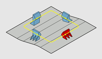
Example of clip mounting seat template created by CATIA
The work of creating the clip mounting seat for the door trim parts, which took 3 days, is completed in 1 minute.
In the development process, we often change the shape variations and dimensions and repeat the examination, and even if we make minor corrections, we may have to recreate the 3D shape from scratch.
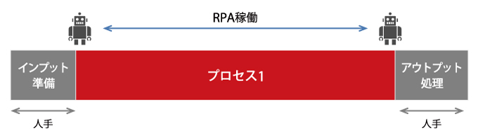
CAD templates are used for each shape, but since they can be reused, 3D shape generation can be simply and instantly completed by changing the parameters of the CAD template used in the early stages of development, while automatically checks the design requirements, production engineering requirements, and mold design requirements.
For automation of calculating values such as the radiator opening area from the modified 3D model, there’s a actual case of work that used to take 3 days has completed in single minute.
In addition, CAD templates can be easily used by anyone who can perform basic CAD operations, so design standardization can also achieve.
Work suitable for CAD template implementation
Since early 2000, SOLIZE has been supporting the development and operation for more than 300 CAD templates in each area of product design, production technology, and mold design for automobile OEMs and automobile parts manufacturers. Past achievements have shown that the following tasks are suitable for CAD template implementation in means of cost-efficiency or return on investment (ROI):
- High frequency feature generation and study such as: Snap fit, boss, mounting hole, clip mounting seat, etc.
- High work load feature generation and study such as: Gradual thickness changing plate, speaker hole and opening area calculation, air conditioner louver and opening area calculation, etc.
- Feature generation and study of parts such as LID: Bumper towing hook cover, instrument panel glove box, instrument panel airbag cover, etc.
- Shapes that incur a large amount of mold repair costs.
For example, in the case of Company A costs 5.4 million JPY / year to study and create the 3D shape of the clip mounting seat.
3 (h / shape) x 60 (location / project) x 3 (development process / project) x 5,000 (yen / h) x 2 (project / year) = 5.4 million yen per year
Those who can perform basic CAD operations, has some idea to develop simple CAD templates, so production of low-cost work shall take by in-house without outsourcing, you can acquire CAD parametric design skills, and man-hours for the entire CAD work reduces.
How to create a simple CATIA template: Snap fit (fitting clip)
This section explains how to create a simple template using CATIA V5.
Unlike ordinary CATIA templates, it does not need to use special licenses (KWA; Knowledge Advisor), so there are restrictions such as the number of shape variations that can be incorporated, or warning (pop-up) could not come out when violates the requirements, but parametric design skills can be acquired. Here, we will create a simple CATIA template using the snap-fit shape model, which is the most popular method for assembling parts.
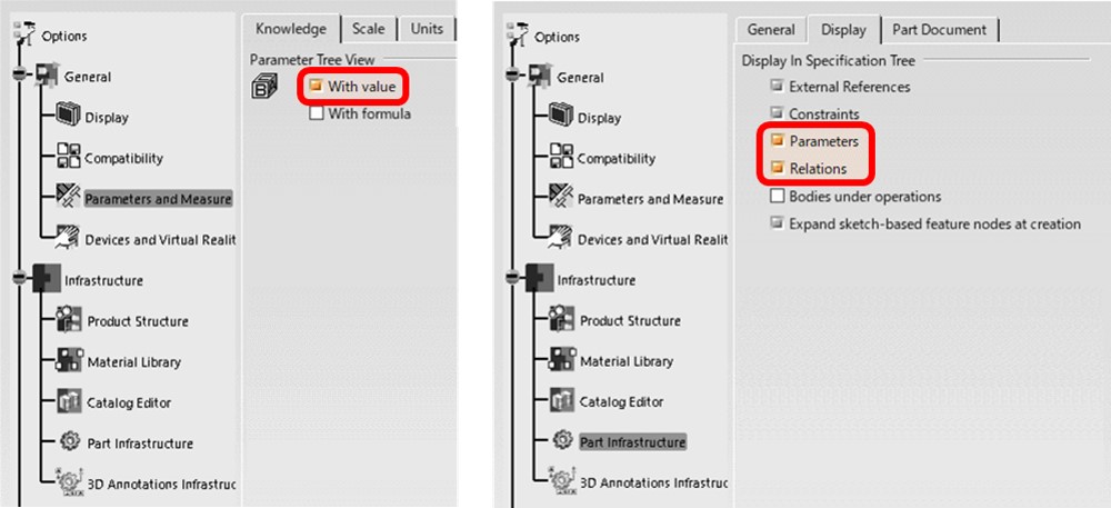
1. Customize option settings
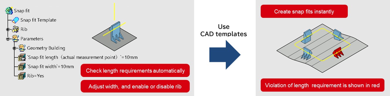
Parameters and formulas (knowledge ware features) are used to automatically check snap-fit length requirements and to change the output accordingly to the given parameters / relations like snap-fit width value and rib enable / disable functions. Customize the following three option settings to applicate the parameters and relations.
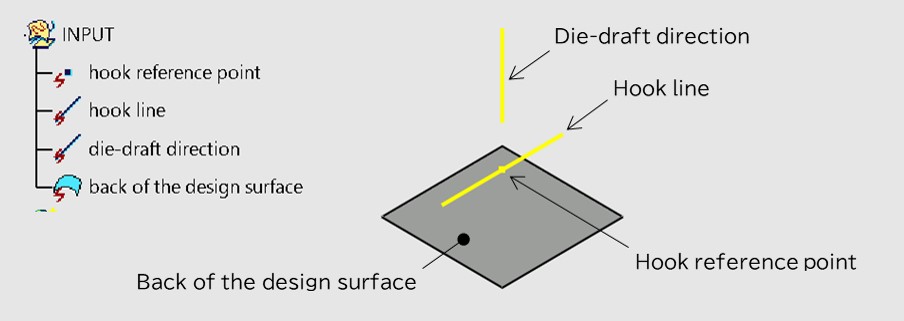
2. Creating an input
Input refers for basic elements to creating a snap-fit template, such as the hook reference point, hook line, die-draft direction, and back of the design surface.
3. Creating snap-fit template: snapping & fitting part
Create a snap-fit shape with the following dimensions based on the input. It is important not to use untraceable non-history elements (internal elements) such as faces, edges, and vertices so that the shape changes as per the input changes. In case if it uses untraceable internal elements, the output will not follow changes with the input.
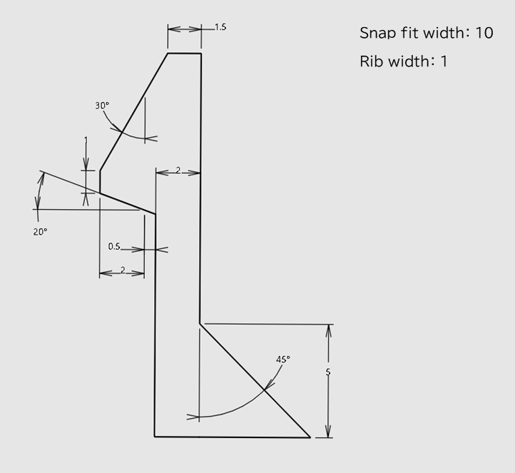
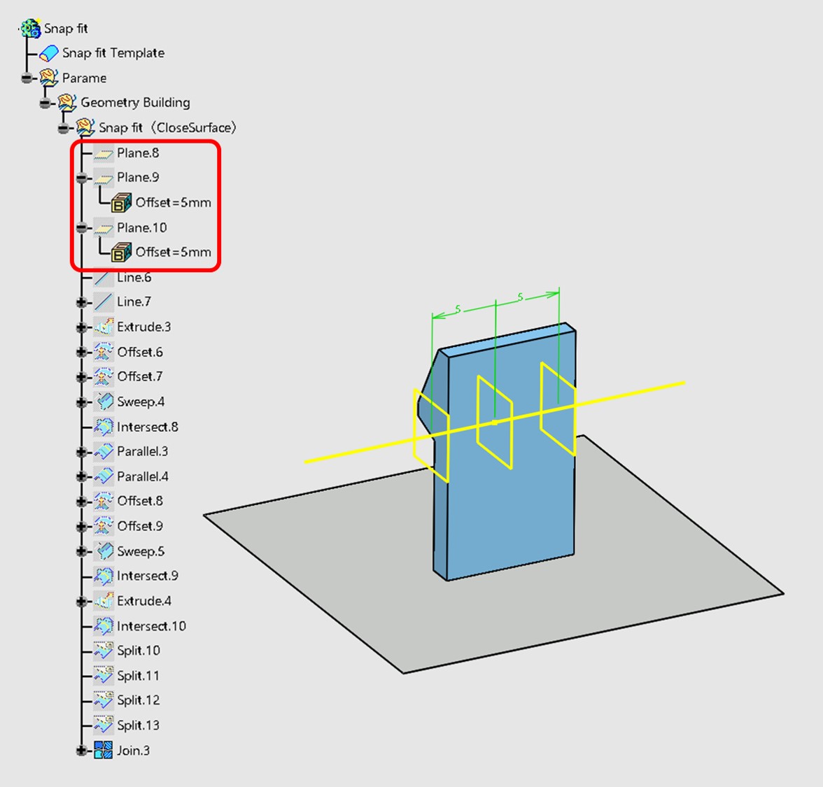
To change the snap-fit shape according to input width, define the snap-fit width using a plane and create a closed surface for the snap-fit based on that plane. Also, defining the width in a plane enhances robustness and makes errors less likely. For example, if you create a snap-fit width of 10mm without defining it in a plane and change the snap-fit width to 20mm, the width will be insufficient and an error will occur.
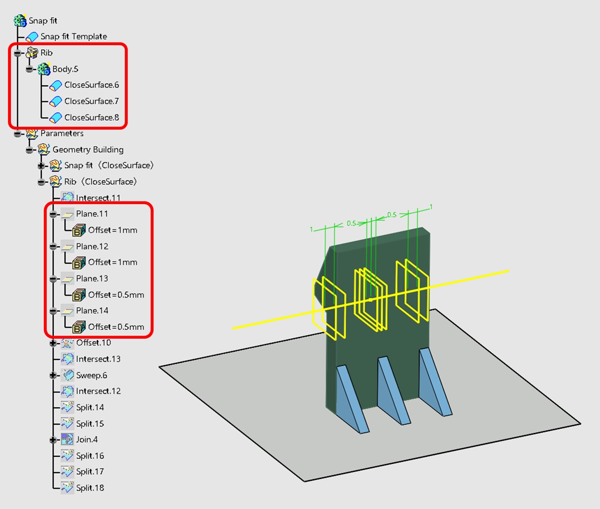
4. Creating a snap-fit template: ribs
Creates the closed surface of the rib as the same method as the snap fit. The rib solids are assembled together so that the shape changes accordingly when the ribs are controlled to be enabled or disabled.
5. Create Snap-fit Template: Parameters
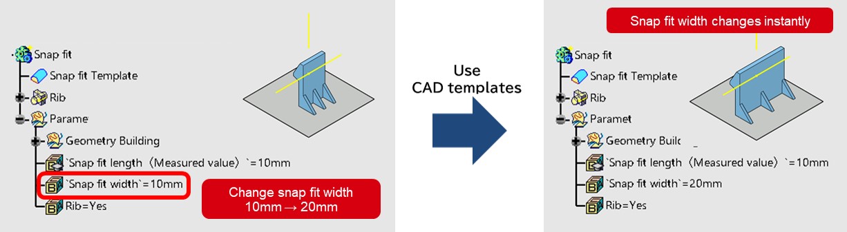
Create a parameter that changes shape following the change in snap-fit width and the enable / disable options of ribs.
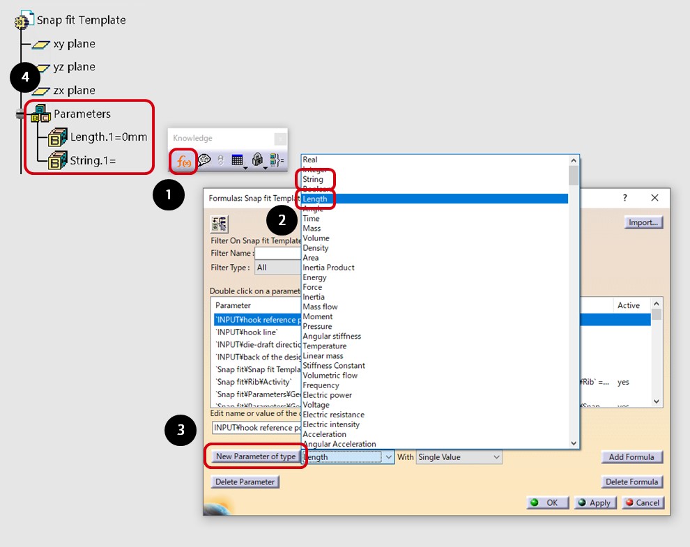
5-1 Create empty parameters
(1) Click the formula icon ❶. The dialog box is displayed.
(2) Add new parameter: Select Length ❷ from Type.
(3) Add new parameter: Click Type ❸.
(4) An empty length parameter ❹ is added to the specification tree.
(5) Add an empty string parameter using the same procedure.
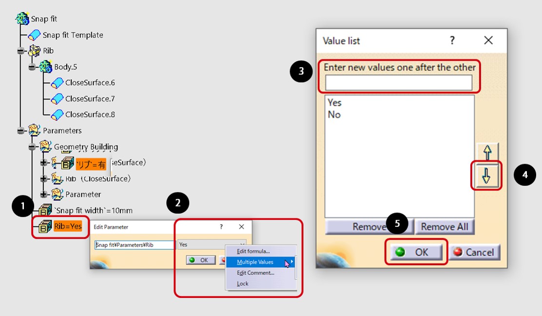
5-2 Add a pull-down menu to an empty parameter
(1) Cut the empty length parameter and string parameter of the specification tree, paste them in the shape set of the template, rename them, and enter the values in the parameters. Add a pull-down menu of "Yes / No" to the rib parameter.
(2) Double-click the rib parameter ❶ in the specification tree.
(3) Right-click in the value field and click Add Multiple Values ❷ from the parameter context menu.
(4) Enter "Yes" for the new value ❸.
(5) Click the down arrow button ❹.
(6) Add "No" in the same procedure.
(7) Click OK ❺.
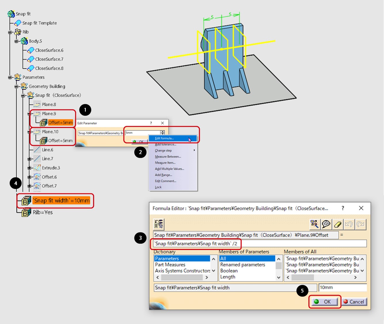
5-3 Create snap-fit width parameters
(1) Double-click the plane of the specification tree. 9 ❶.
(2) Right-click the value field and click Edit Expression ❷ in the parameter context menu.
(3) Click the snap-fit width parameter ❹ in the specification tree to substitute it in the expression editor ❸. Then enter "/ 2".
(4) Click OK ❺.
(5) Add the plane .10 of the specification tree in the same procedure.
(6) Change the snap-fit width parameter ❹ to "10mm → 15mm" and check that the shape changes accordingly.
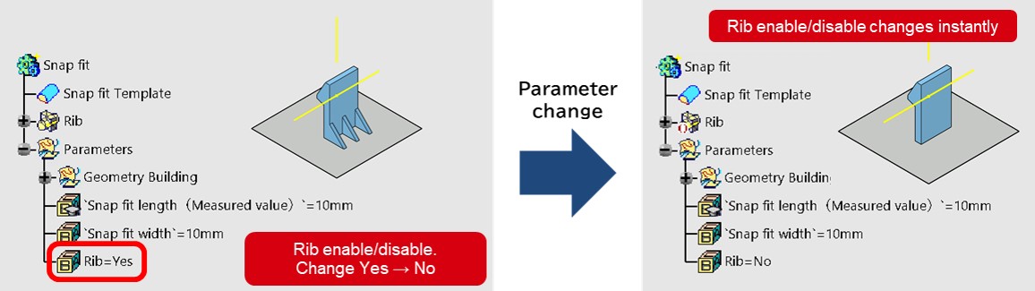
5-4 Create parameters with and without ribs
(1) Click the formula icon ❶.
(2) Click Rib Assembly ❷ from the specification tree.
(3) Add formula ❸ Click.
(4) Click the rib parameter ❻ from the specification tree to assign it to the expression editor ❹. Then enter "==" Yes "".
(5) Click OK ❺.
(6) Change the rib parameter ❻ from “Yes → No” and check that the shape changes accordingly.
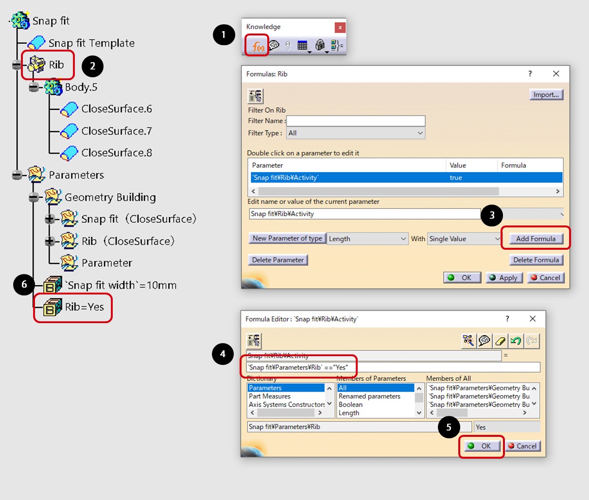
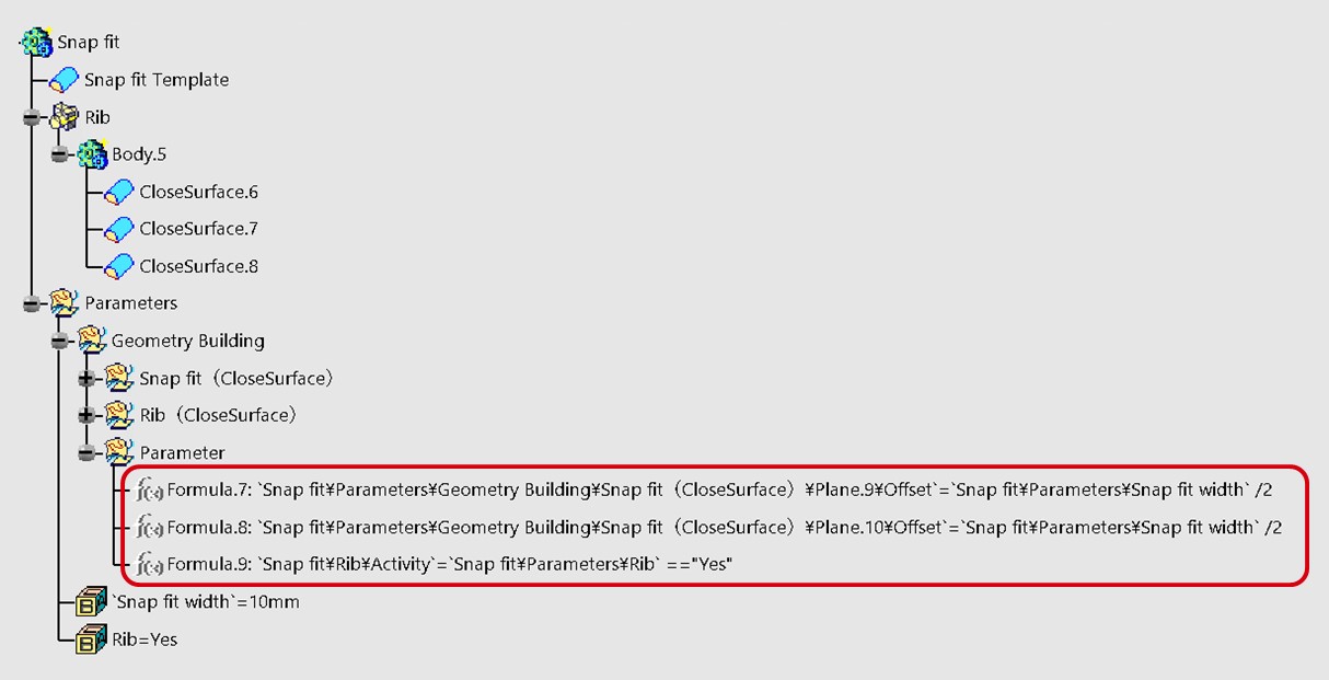
(7) The created parameter expression is added to the specification tree. Cut out all the formulas and paste them into the template shape set.
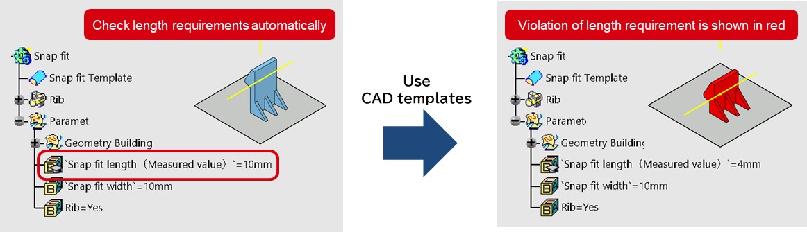
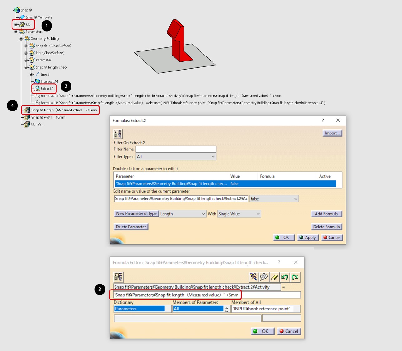
6. Create snap-fit template: Snap-fit length check
Create a parameter that automatically checks the snap-fit length requirement. This time, we define as if the snap fit length is less than 5mm will be a violation of the requirement, and it will be created in red.
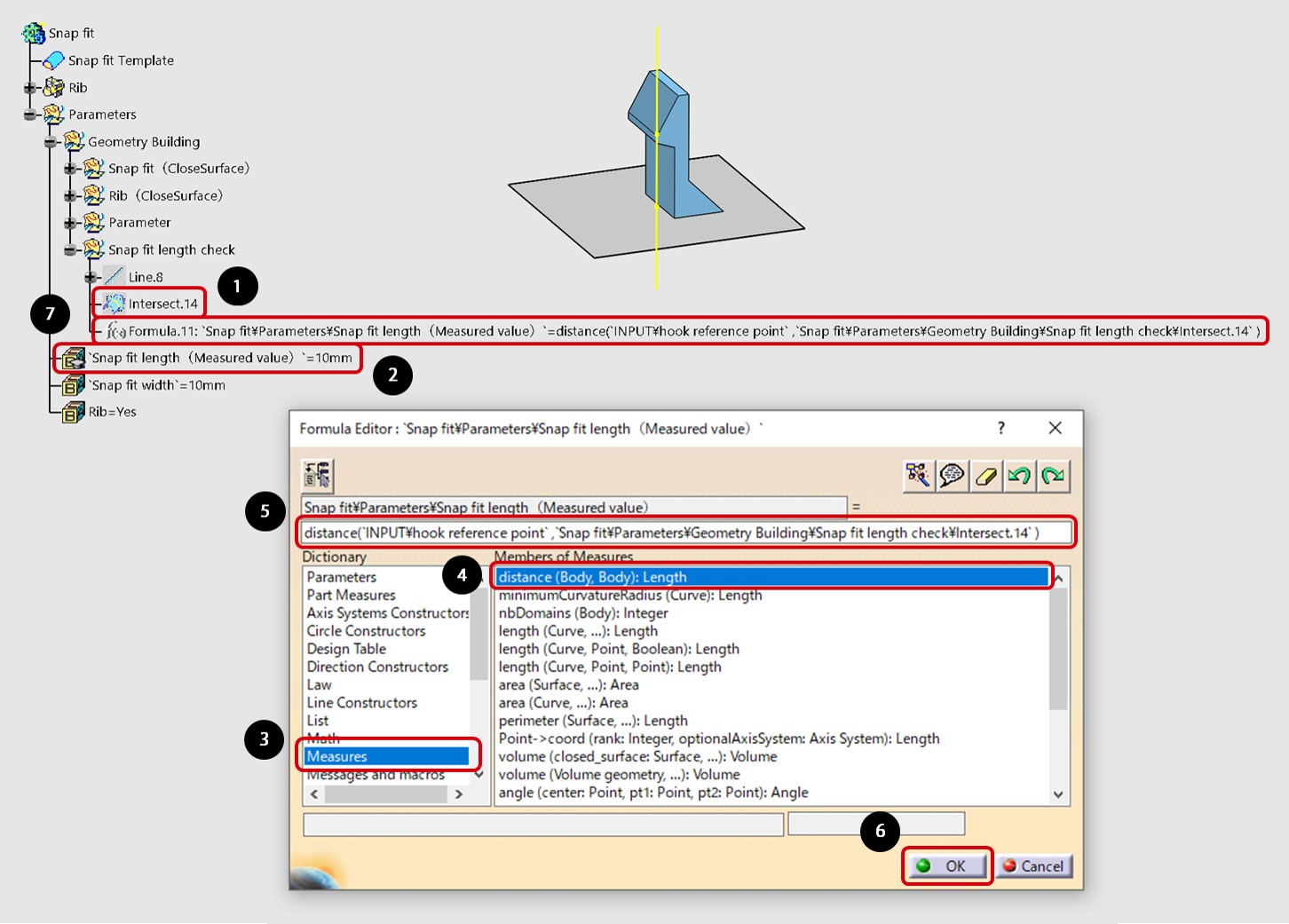
6-1 Assign the measured value of snap-fit length to the parameter
(1) Create the actual measurement point ❶ of the snap fit length.
(2) Add the snap-fit length parameter ❷ to the specification tree in the same procedure as the snap-fit width parameter.
(3) From the snap-fit length parameter ❷ in the specification tree, click Edit to display the Editor.
(4) Select Dictionary measurement ❸.
(5) Double-click "distance (body, body): length" ❹ from the list of dictionary.
(6) Click the reference point from the input of the specification tree to substitute it in the formula editor ❺. Then click the actual measurement point ❶ to substitute.
(7) Click OK ❻. The measured snap-fit length is now assigned to the parameter.
(8) Cut the formula created in the specification tree and paste it into the parameter shape set ❼.
6-2 Modify created feature’s color in red if snap-fit length violates the requirements
(1) Click Rib Assembly ❶ from the specification tree to extract ❷.
(2) Change the color of Extract ❷ to red.
(3) From here, the procedure is the same as "5-4 Creating parameters for the presence or absence of ribs". Click snap-fit Length ❹ from the specification tree to assign it to the Expression Editor ❸. Then enter "<5mm". With this, if the measured value of the snap fit length is less than 5 mm, it will be automatically judged as a requirement violation and the red extraction will be displayed.
7. How to use snap-fit template
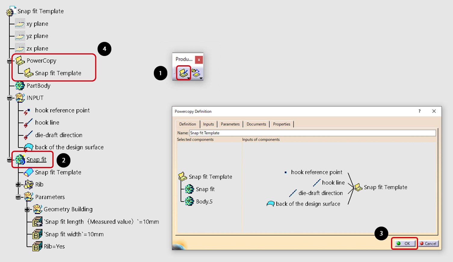
7-1 Make a power copy
(1) Click the Create Power Copy icon ❶ and select snap-fit Body ❷ from the specifications tree.
(2) Click OK ❸ to make a power copy.
(3) Power copy ❹ is added to the specification tree.
7-2 Utilize snap-fit templates
(1) Create input ❶ in the file for which you want to use the snap-fit template.
(2) Click the copy command ❷ of the shape feature set in the file for which you want to utilize the snap-fit template.
(3) Select Power Copy ❸ from the snap-fit template file.
(4) Select the input ❶ corresponding to the input field ❹ in the dialog box. When selecting line or surface elements such as Snapping edge, die-cut direction, or the back side of design surface, align the green arrow ❺ with the red arrow ❻. If the arrows have different orientations, click the green arrow to align the arrows.
(5) Check Repeat ❼ so that you can repeat the use of the snap-fit template.
(6) Click OK ❽.
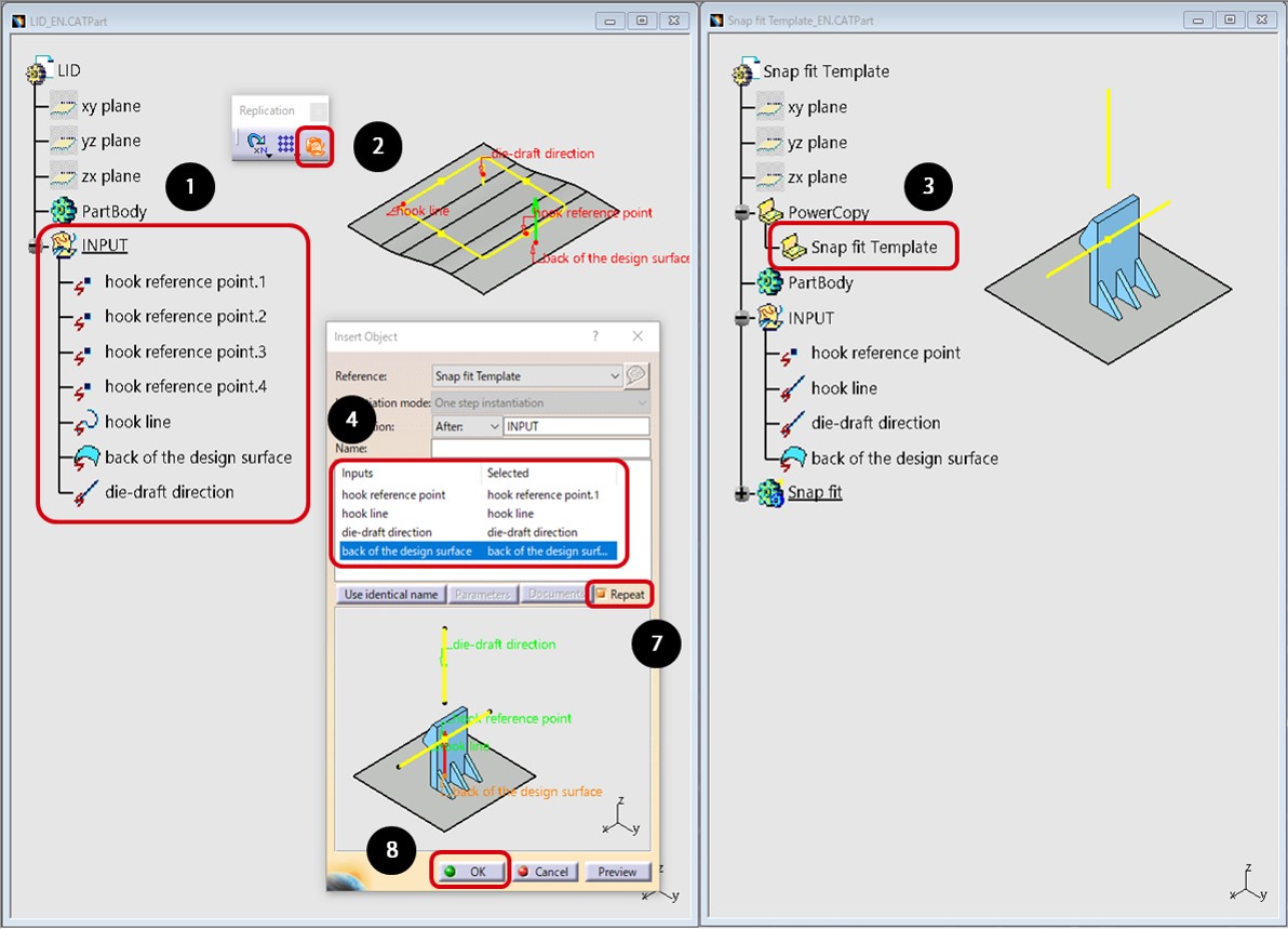

(7) A snap-fit is created in the file for which you want to use the snap-fit template.
(8) Select the hook reference point .1 in the input field ❹, and select the hook reference point .2 ❾ from the specification tree to substitute.
(9) Click OK ❽. Repeat until the hook reference point .4.
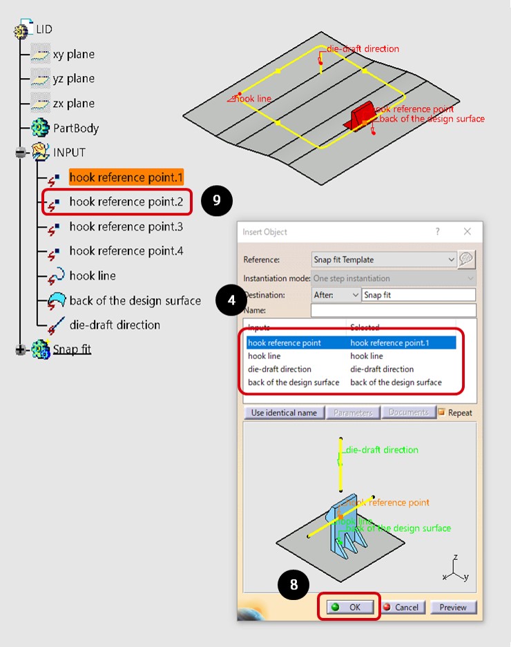
(10) All snap-fits are created in the file for which you want to use the snap-fit template.
◆◆◆
SOLIZE supports the efficiency of design work using CAD templates. Please feel free to contact us if you have any problems or inquiries, including how to create a simple CATIA template.
3DEXPERIENCE, Compass Icon, 3DS Logo, CATIA, BIOVIA, GEOVIA, SOLIDWORKS, 3DVIA, ENOVIA, EXALEAD, NETVIBES, MEDIDATA, CENTRIC PLM, 3DEXCITE, SIMULIA, DELMIA and IFWE are Dassault Systems in the United States or other countries. A registered trademark or trademark of a European company in France) or its subsidiaries, registered with the Versailles Commercial Registry under registration number B 322 306 440.